Tuesday, November 19, 2019

Progress for 11/20/19

Goals for 11/20/19:

  • Set HX711 pins to digitalread configuration, to collect the raw data and try to see if that fixes the issue of slow performance of the code
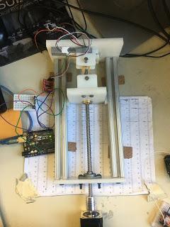
  • Verify that motor travels to the appropriate distance under the appropriate time duration. 
Code for the week can be seen through this link under 11/20:


Results:
  • Tested out the digitalRead configuration by removing the scale.get_units() function and replacing it with digitalRead(DOUT) and digitalRead(CLK)
    • DOUT in this case is the digital output pin of the HX711 
    • CLK is the serial input for the HX711
    • Based off of the HX711's datasheet, CLK and DOUT are used for data retrieval, input selection, gain selection, and power down function
  • However, when the code runs, the only value that is displayed in Arduino's serial port is just 1. 
    • This is wrong because even when I apply more or less force to the device, the serial port still reads 1. 
  • Then troubleshooted and researched the HX711's functionality and Arduino syntax
    • Used a different HX711 to see if maybe that's the problem, but it's not because it gives the same output
    • Found out that since DOUT and CLK is placed on a digital pin, it will only give values of 0 or 1 (OFF/ON) on the Arduino's serial port. 
    • I also thought maybe I have to calibrate the system by moving it at different distances, but it wouldn't help the problem because I'm getting 1s not matter what I do. 
    • Tried putting DOUT and CLK on analog pins, but I only viewed values of 0 on Arduino's serial port. So, I've come to the conclusion that there's something in the HX711 arduino library that I'm missing out on.
  •  I started researching the HX711's functionality and the HX711 Arduino library to try to find out what I'm missing in my code that, the function scale.get_units() refers to. My objective with doing this is to see if I can hard code whatever its referencing and see if it improves the code's performance. 
    • Found out that the way the HX711 works is that data retrieval only begins for the HX711 when DOUT is set to LOW
    • When DOUT is set to LOW, 25-27 pulses are sent to the CLK pin and data is shifted to the DOUT pin.
    • So, with this information I could try setting the digital pin to LOW and see what happens? But, if nothing happens at that point, the load cell might not be receiving enough current and i have to change the gain????
    • MatLAB also has a built in arduino add-on for the HX711, so maybe I could try that too??????? 
  • Other than my troubleshooting activities, I also performed verification testing to see if the motor moves the device the appropriate distance during the correct calculated time. My efforts can be seen here: 
    • https://docs.google.com/spreadsheets/d/1Qps9yNjCzT_4Mehc4KnrKgyOdZEeMLO36xrFZnCQQz8/edit?usp=sharing
    • This table shows what input parameters, predictions, and output parameters I specified:
      • INPUTS:
        • Distance I want it to travel in cm
        • How many cm do I want the motor to travel across a certain number of seconds (Speed)
          • 1 cm over 4 s= 0.25 cm/s
          • 5 cm over 30 s = 0.1666666667 cm/s
        • Load Cell Frequency
          • How often do I want load cell samples to be sent to the serial port
          • Compared 10 load cell samples sent vs 100 load cell samples sent
      • PREDICTIONS:
        • Time(s)
          • Calculated by dividing the specified distance by the defined speed
          • Verifies between different distances chosen
      • OUTPUTS:
        • Actual time it takes for the code to be performed for each distance
      • PERCENT ERROR CALCULATIONS:
        • Comparison to see how much the predicted and measured values deviate from one another. 
        • Percent Error Equation: abs(measured value-actual value)/ actual value *100
          • Measured value in this case: Predicted Time or Specified Distance
          • Actual Time: actual time it takes the code to be performed or actual distance traveled
CONCLUSIONS:
  • Need to find out best way to integrate HX711 into the system without slowing down the code's performance and provide interpretable values for the users :(((( 
  • Percent Error calculations from verification testing shows that the code can accurately perform or travel the appropriate distance. However, there is a significant difference between the actual and measured time values. This difference may be attributed to the delays defined in the code? But, this might not be the case and it just might be the time it takes for the code to perform because I removed the delay lines in my code and it functions the same. 

GOALS FOR NEXT WEEK:
  • Figure out the best way to integrate the HX711 into the system help

RELEVANT LITERATURE THAT HELPED ME THIS WEEK:

http://image.dfrobot.com/image/data/SEN0160/hx711_english.pdf

https://drive.google.com/drive/u/1/folders/1n60yP_wW-bhL4Cr68UYc9ab6dijqGEEq


https://github.com/bogde/HX711/blob/master/README.md


Tuesday, November 12, 2019

Progress Report for 11/13/19

Goals for 11/7/19-11/13/19:
  • Tested out more speeds to see which was the fastest at defined frequencies
  • Perform tests to observe different relationships between high or low MHigher M

  • Verify that it works and that it meets the appropriate time and defined parameters
  • Figure out/troubleshoot what is going on with the Arduino/Matlab interface, specifically the COM9 erro
Codes used for the week can be found under this link under the appropriate date (11/6/19):
Progress for the week of 11/7/19-11/12/19:
I started this week off by really trying to understand the sampling frequency rate (relationship between motor steps and load cell samples).
To observe how changing this value will affect the tester’s performance. To do this, I did several things:
  • I chose one appropriate speed(S) for the motor (how far should the motor go/how many seconds eg. 4cm/30s).
  • For this step, I chose S to be 5 cm/ 30 seconds
  • Choose what distance I wanted the motor to travel (D)
    • 1 cm 
    • 1 cm correlates to 1000 steps (steps)
  • Find values for TM   and Tlc 
    • TM   is dependent on the chosen speed(S) and the calculated step rate(A)
    • In this case, since I left it consistent A= 166.6667 steps/s 
    • ™   is then equal to the inverse of the speed rate value multiplied by a 1000
    • As for Tlc, I just had to choose what frequency I wanted load cell signals to be sent to the serial port(Flc)
      • Since, I wanted to see the different relationships of having a large or small M, I chose varying frequencies for Flc
        • These varying frequencies range from 10-100 with increments of 10 Hz
    • The values I used and the results I received from these tests can be seen under this link:
  • After I performed the proper calculations, I performed my tests with these values and tried to verify if it worked appropriately. 
    • Does the program perform/execute the code during the predicted time duration?
    • Does the motor meet the appropriate distance specified by the correct number of steps?
  • To verify this:
    • I first changed the necessary parameters
      • TM
      • Tlc
      • Distance/number of steps
      • Flc
    • Add a timer to Arduino’s serial port to observe how long it took
      • In my progress report code the line that correlates to this action is: Serial.print(millis()). 
    • Place a ruler under the testing system to see if the motor travels the appropriate distance
      • This is the test setup:
  Figure 1: Tensile Tester test setup to verify that the motor moves the system to the appropriate distance.
In this image, a ruler was placed under the tester to serve as a verification method
  • Results of my tests show that: 
    • For each test performed, I found that my Arduino timer was consistent.
      • Code was accomplished within 96000 ms (1 min and 36 seconds) regardless of what frequency I chose for Tlc, it was always the same!
      • I found that to be interesting because this measured time duration did not match my predicted time duration of 6 seconds.
        • It was off by 60% which was very alarming to me
    • With this information I started troubleshooting my code because I believed that my interpretation of what needed
    • to be done and my calculations were correct, so there was something definitely off. 
  • Code Troubleshooting:
    • I first started reorganizing my code to see if things needed to be defined earlier or later or if things needed to be removed, etc.
    • After that, I started looking at my previous codes that I designed for the motor (insert delay stepper code here) to see what am I doing differently
    • that might be throwing off the code.
    • The main differences between my previous and current code is that the use of a for loop within the void setup in place of the void loop.
    • While in my current code, I’m using the void loop and several conditional statements to serve as an on/off switch to signals
    • Knowing the differences between these codes, I tried taking out the motor and load cell functionality
    • outside of the void loop and just in the void setup
      • I found that it functions the same and that there is no complete difference in terms of performance of the motor
    • After this, I tried commenting out different sections of my code to see if anything will change. 
      • I commented out the Load Cell functionality code and I found that this line of code was slowing down the performance of the motor!!!
        • Serial.println(scale.get_units(1,1)) 
    • So, now my line of action is to find a way to work around this issue and see what will be best.


Sunday, November 3, 2019

Progress Report for 11/6/19

    Goals to accomplish for the week of 10/31/19-11/06/19:

  • Verify code works and travels the appropriate distance and speed
  • Configure code with MATLAB??
Copy of code used this week can be found under this link under the appropriate date (10/31):https://docs.google.com/document/d/13rn23kiAMY7ovi3cRF-_pt-kocN8uBqWrs1T-pzl6as/edit?usp=sharing

Progress for the week of 10/31/19-11/06/19:


  • Troubleshooted code with Professor Leineweber/addressed issues with my misunderstanding of concepts particularly in relation to calculations/conversions for input, motor, and program parameters

  • Results of conversions and calculations can be found under forward/backward calculations: https://docs.google.com/spreadsheets/d/1sg0LK4XL-QSUAAPrCIgS7ezz7kZ2D-F2YC9tgsCq91E/edit?usp=sharing

  • Input Parameters:  user-defined parameters that define the relationship of other parameters (Motor parameters, conversions, etc.). It’s basically the independent variable of the code. 

  • Travel Distance (D): how far the user wants the motor to travel (can be in mm, in, cm, etc)

  •  For my experimental purposes I’m currently using cm. Will eventually move to mm

  • Travel Speed (S): user determines how fast he/she wants to attain the selected distance (In the calculations, it’s measured in cm/s) 
        • How many cm do you want the motor to travel over x number of seconds 
          • E.g. 5 cm/ 5 s
          • Note: High speeds leads to less torque 
            • I need to find an optimal that is fast enough for my purposes, but not too fast that it significantly decreases the motor’s torque 
            • Frequency of load cell and motor cell can also affect the speed
    • Motor Parameters: segment of the code that defines what variables need to be established to define the motor’s function. These values are constant.
      •   Step Resolution (R): how many steps does the motor need to perform for it to complete one revolution 
          • This value is equal to 800 steps/rev
      • Lead Screw Pitch (P): the distance between threads  
        • This value is equal to 0.8 cm/rev
      • Conversions: calculations conducted to ensure everything is in the appropriate units that the program (Arduino IDE) can interpret and also into necessary values that need to be inputted into the code to define the motor/load cell’s function. 
        • Steps traveled(N): Motor interprets distances in steps. This value is attained by multiplying the travel distance (d) by the step resolution ® and then dividing that value by the lead screw pitch (P)
          • N=(D*R)/P
        • Step Rate (A):how many steps the motor must perform over a set number of seconds. This value is attained by multiplying the speed (S) by the step resolution ® and then dividing that value by the lead screw pitch (P).
          • A=(S*R)/P
        • Test duration (time): defines how long it will take for the motor to travel a specified distance (D) at defined speed(S). This value is calculated by dividing steps traveled (N) by step rate (A).
          • time=N/A
      • Program Parameters: user defined parameters needed to serve as blocking and for easy manipulation of the code. It’s also to define how often signals from the load cell and motor are sent to Arduino’s serial port. Load cell frequencies should be more frequent than the motor. 
        • Step Delay (™): used to block the motor’s function; after the motor completes one step, the code will stop the motor’s function for x ms based off of this value. This value is calculated by taking the inverse of the step rate (A).
          • 1/A
        • Load Cell frequency (Flc): user defines how often he/shwants load cell signals to be sent.
        • Load Cell Delay (Tlc): delay period of the load cell. similar to step delay except for the load cell; used to block the load cell’s function; after the load cell has completed its intended function, the program will stop the load cell’s function for x ms based off of this value. This value can be calculated by taking the inverse of load cell frequency (Flc)
        • Samples per step (M):defines how many load cells samples should be sent to the serial port in relation to a certain number of steps. This value is calculated by dividing step delay (™) by load cell delay (tlc)
          • M=Tm/Tlc

    I initially tested the system using these values for U,D,N, ™,TLC and M respectively: 13.3 RPM, 1cm, 1000 steps, 5 ms, 10ms, and 0.5. But, I found that this rate was too slow

    • Although, I did not find the proper optimal speed for the motor (yet), I wanted to check if my Arduino code worked appropriately with a MATLAB code that my peer developed for the manual tensile testing system last year (See code here:). To do this, I placed 4 rubber bands in tension on the tensile testing system to see what would happen.
    Figure 1: Experimental Test Setup to see if the MATLAB and Arduino codes can be used together. This setup has the motor and load cell connected to two separate boards. The mounting block on the tensile tester is placed at 0 cm on the "ruler" and four rubber bands are placed in the system. 

    Figure 2: Zoomed in experimental set-up of the MATLAB/Arduino Test. From this image, it can be seen that the tensile tester's mounting block is placed "zeroed" out prior to the test to observe what distance the tester will travel. This image also shows how four rubber bands are used for this experiment. These rubber bands are not placed in tension yet.
    • To test this I initially put everything into one circuit and on one Arduino Uno board, but for some reason when I tried to use the MATLAB and Arduino codes together I got this error message on the Arduino side: “COM9 restricted
    • As a result, I ended up connecting the motor and the load cell on two different Arduino Boards/ computers and tried to see if I would get any results (See Figure 1)
      • My experimental tests can be seen in the videos below:


      • Video 1 initially shows my experimental setup of the test (showing how everything is connected) and how the MATLAB/ Arduino Interface looked. The stepper motor was set to 13.3 RPM, 1000 steps(1 cm), TLC=10ms, and TM=5 ms. As you can see the stepper did move 1 cm, it moved at a slow rate, and the rubber bands were slowly being stretched.
      • Video 2 shows the same experimental test and set up, however the 4 rubber bands were already stretched out by 3 cm. 
      • My experimental tests weren’t a complete failure, it just highlighted some issues that I need to address and figure out moving forward.
      • Goals for next week:
        • Tested out more speeds to see which was the fastest at defined frequencies.
        • Perform tests to observe different relationships between high or low M 
          • Higher M= ™>TLC
          • Lower M=™< Tlc
          • Show graphs here(insert picture here)
        • Calculated experimental speeds and frequencies can be seen under Speed/Frequency Conversions under this spreadsheet link:https://docs.google.com/spreadsheets/d/1sg0LK4XL-QSUAAPrCIgS7ezz7kZ2D-F2YC9tgsCq91E/edit?usp=sharing
        • Verify that it works and that it meets the appropriate time and defined parameters
      • Figure out/troubleshoot what is going on with the Arduino/Matlab interface, specifically the COM9 error 

      Progress for 11/20/19

      Goals for 11/20/19: Set HX711 pins to digitalread configuration, to collect the raw data and try to see if that fixes the issue of slow p...